

SPRINGFIELD ARMORY XDS DETAIL DISASSEMBLY PT. 3 OF 6 Slide
Springfield XDS Slide Detail Disassembly
This is part 3 of a 6 part article series focusing on the complete 100% detail disassembly of the Springfield Armory XDS pistol. If you can not easily find the other sections use our search icon on the top right of the website. Type in "XDS Detail Disassembly" and we will provide you with the complete series.
We have broken the six part series into the following sections to make it easier to follow and focus on the following areas.
Sections:
- 1. Magazines
- 2. Field Strip
3. Slide Disassembly
- 4. Striker Disassembly
- 5. Frame Disassembly
- 6. Sear Housing and Trigger Disassembly
Note:
- Springfield Armory does not recommend further disassembly of the frame. "Further dismantling is not necessary and should only be done by Springfield, Inc. or a qualified pistolsmith". Pg 26 XDS operation and safety manual.
- These instructions are for informational use only and should only be attempted by trained individuals. If you are unsure and/or do not have the right tools and training please do not attempt.
The following step are for the complete 100% disassembly of the Springfield Armory XDS pistol. The disassembly procedure will be spit into 6 parts focusing on the different assemblies and areas of the pistol.


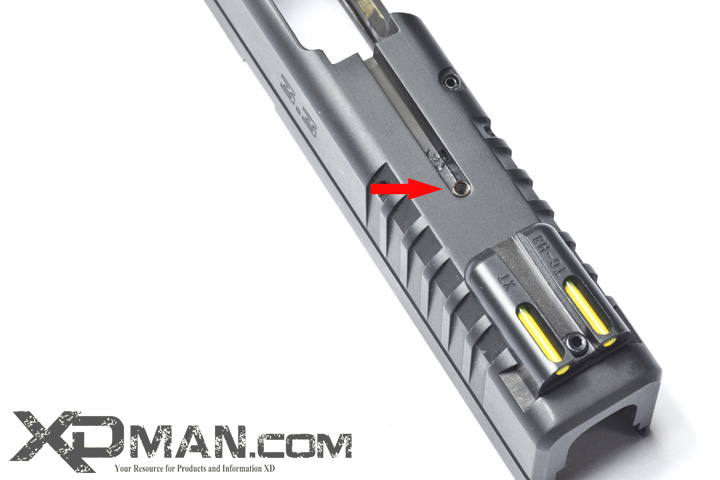
Left red arrow is highlighting the slide disassembly button. The striker locking plate is held in place by the striker guide. Using an XDS Striker Button Tool we made & Armorers Cup we have elevated the slide enough to allow us room to work and push the disassembly button in. This releases the striker locking plate. Most of the time as soon as you push the disassembly button in, the striker locking plate will just fall off the slide. If the plate gets stuck just pull it down off the back of the slide (far right image).


Left: The striker locking plate has been removed from the slide exposing the back end of the striker assembly. Middle: Pull the striker assembly out of the back of the slide. Far right: the striker locking plate, striker assembly and slide in order of disassembly/reassembly.
Note:
- You will feel a slight resistance when pulling the striker assembly out and putting it back in, this is normal.


Left: Red Arrow is showing you the location of the loaded chamber indicator pin (LCIP). Center: To remove the LCIP tap it out from right to left as if you were shooting the pistol. Start from the ejection port opening and tap away from it. NOTE CENTER BLUE ARROW-from the factory the LCIP is given a small detent.. This side of the pin is the last to go in the slide when you reassemble. If you put the detent in first and pound the pin in you will most likely get the pin stuck in the slide and it will be almost impossible to remove. When you reassemble put every thing back together opposite of taking it apart taking extra care to make sure that detent goes in last. Right: A gunsmiths trick of letting the punch be a third hand and holding things in place.


Carefully remove your punch and use your finger to tip the end of the loaded chamber indicator and pull it out of the slide. With the indicator removed the (center red arrow) Loaded chamber indicator spring is revealed. Carefully remove the spring taking care not to lose this small part.
The Loaded Chamber Indicator consists of three parts:
- loaded chamber indicator
- loaded chamber indicator pin
- loaded chamber indicator spring.


Next we will remove the extractor assembly. Left arrow is showing the position of the extractor just behind the ejection port of the slide. To remove the extractor you have to locate the extractor roll pin on the bottom of the slide shown by center arrow. Take your punch and tap the roll pin from the bottom towards the top of the slide. The bottom of the hole is smaller than the top of the hole so you have to start from bottom and tap the roll pin towards the top. BE CAREFUL: The extractor holds the striker pin safety in place (little silver ball looking thing on the bottom of the slide next to the extractor roll pin). If you let the extractor go too quickly the safety can go flying and get lost.


Left: Tap the extractor roll pin from the bottom of the slide. Center: Leave your punch in the slide to hold the extractor in place. Right: Use your hand to cover the bottom of the slide then remove the punch. Most likely as soon as you pull your punch out, the striker pin safety and spring will want to fly out of the slide.


Left: The red arrow shows the striker pin safety position. With the extractor removed, you can now see the striker safety spring that was hidden by the extractor. To the right you see the striker pin safety and spring then the extractor, extractor spring and extractor spring rubber.
The Striker safety consists of two parts
striker pin safety
striker safety spring
The Extractor assembly contains 4 parts
extractor
extractor spring
extractor rubber spring
xtractor roll pin


The dovetail of the XDS is not tapered so it does not matter which direction you remove the sights. They are put on the factory Left to right and most after market sights are installed from left to right because they have a leading edge to help start the sights in the dovetails.


Since the dovetails are not tapered it does not matter which direction you remove the sights from. For installation check with the manufacture of the aftermarket sights and see what they recommend. Most aftermarket sights will have a tapered edge to help start the sight in the dovetail. If you need sights or an install don't hesitate to come see us at our sister website www.xdman.com we are experts at what we do.


